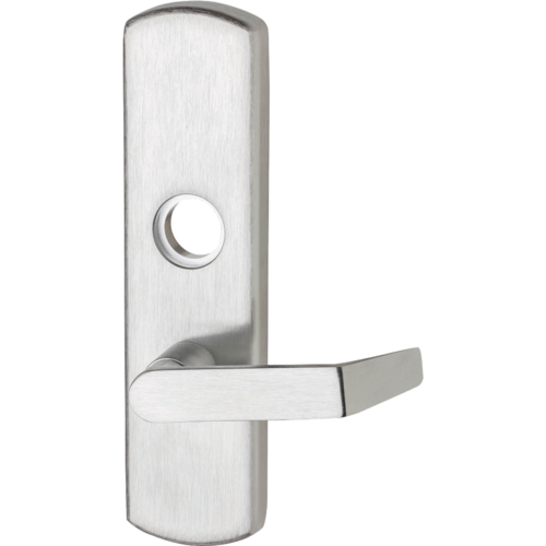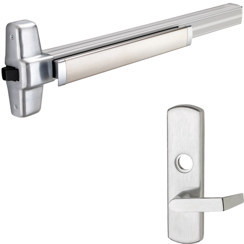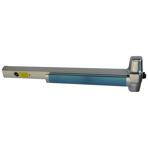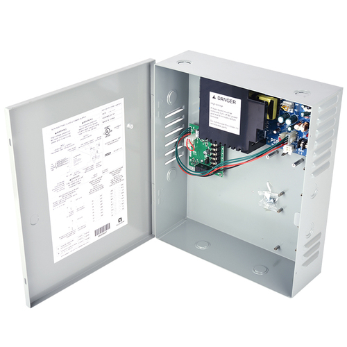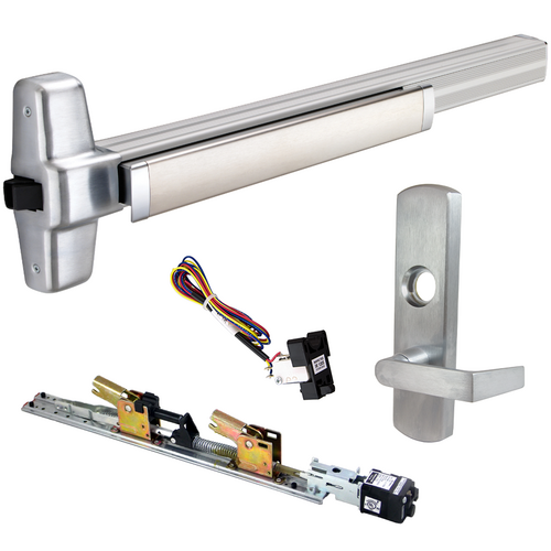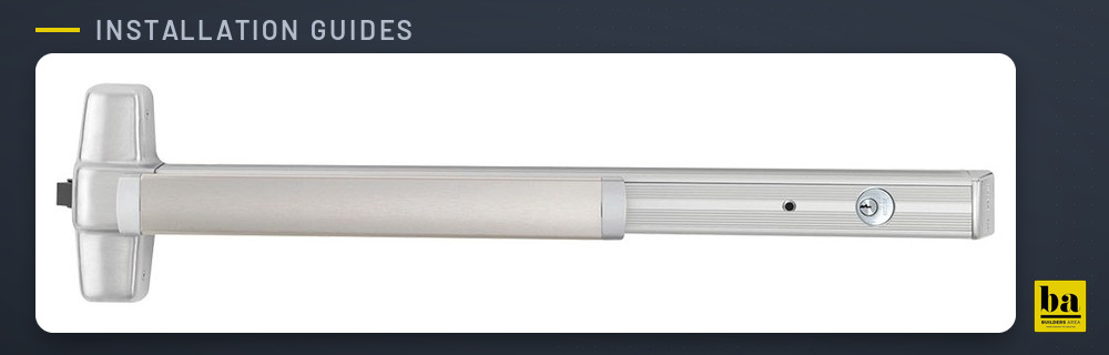
The Von Duprin Chexit is a delayed egress exit device. According to Von Duprin's installation instructions, it sounds an alarm and keeps the exit door secured for 15 seconds after someone tries to exit, and it releases immediately when the building fire alarm is activated.
This page summarizes the manufacturer's document "Installation Instructions - Electrical" for the CX33A/35A and CX98/99 Chexit device (document 911352-00, 8 pages) and shows where to find each topic in it.
Download the Von Duprin Chexit CX98/99 manual (PDF, 8 pages)
Which devices this manual covers
The cover of the manual names the CX33A/35A and CX98/99 Chexit devices. The Chexit devices in our catalog today carry the CXA prefix, for example CXA-99EO. For a CXA device, follow the instructions packed with the device. If you are not sure which instructions apply to your hardware, contact Von Duprin or call us before you start.
What is in the Chexit manual
- Page 1: general information and electrical specifications
- Page 2: pre-installation checklist (mechanical and electrical preparation)
- Page 3: wiring diagram for a single door and the table of installation components
- Page 4: wiring diagram for double doors, wiring requirements and wire functions
- Pages 5-6: installation of the Chexit module in 10 steps
- Page 7: operation (summary of Chexit modes) and troubleshooting
- Page 8: option switches and rearm time settings
Electrical specifications
From page 1 of the manual:
- Voltage: 24 VDC
- Current: 0.4 A
- Current on arming: 16 A in-rush for 300 ms
- External alarm dry contacts (NO and C): rated 24 VDC, 1 A
- Normally closed inputs: fire alarm (required), external inhibit, door position switch
Chexit wiring diagram: wire colors and functions
The wiring diagrams are Figure 2 (single door) and Figure 3 (double doors). Page 4 lists the function of each wire in the Chexit cable:
- Red (+24): power supply +24 VDC
- Black (GND): power supply ground
- Blue (C): common for the normally open output, 24 VDC, 1 A maximum
- Brown (NO): normally open output, closes during alarm
- Violet (CM-) and gray (CM+): communication lines used to connect two Chexits; if they are not used, the manual says to insulate them separately
- Yellow (FA): fire alarm input
- Orange (DPS): door position switch input
- Green (EI): external inhibit input
- White (SC): signal common +24 VDC, which can be used to power the FA, DPS and EI inputs
The manual states that components must be connected to the wire colors shown in Figures 2 and 3.
Components shown in the wiring diagrams
Table 1 on page 3 lists what the installation uses:
- 24 VDC power supply: required. The manual names the Von Duprin PS873.
- Building fire alarm with normally closed contacts: required. It unlocks the Chexit in case of a fire alarm.
- Power transfer (EPT-10 shown): highly recommended. If it is not used, the manual calls for a door loop or an electric hinge.
- External inhibit device such as a card reader or key switch, with normally closed contacts: optional. It allows authorized egress or ingress without an alarm.
- Door position switch with normally closed contacts: optional. It arms the Chexit 2.5 seconds after the door closes and sounds the alarm if the door is forced open.
- External alarm: optional. It provides a louder alarm than the internal horn.
Table 2 on page 4 gives the wiring requirements for the power supply output. With an EPT-10 power transfer, a run of up to 100 feet from the power supply needs at least 14 gauge wire and a run of up to 200 feet needs at least 12 gauge. With an electric hinge, the limits are 75 feet for 14 gauge and 150 feet for 12 gauge. The wiring for the external alarm, fire alarm, door position switch and external inhibit device is listed as 18-22 gauge.
How the Chexit operates
Page 7 summarizes the modes of the device:
- Rearm: after the Chexit is turned on with the key switch, the pushpad stays unlocked for the rearm time (0 to 28 seconds).
- Armed: the pushpad is locked and the red LED flashes slowly.
- Release delay: when the pushpad is pressed, the alarm sounds and the pushpad stays locked for 15 seconds.
- Alarm: when the 15 second delay expires, the pushpad unlocks and the alarm continues.
- Inhibit: turning off the key switch or activating the external inhibit unlocks the pushpad with no alarm.
- Fire alarm: when the fire alarm contacts open, the pushpad unlocks.
For a pair of doors, the manual shows two Chexits connected by the gray and violet wires. When one goes into alarm the other does too, and both unlock after 15 seconds. The manual requires the rearm times of the two connected Chexits to differ by at least 2 seconds.
Option switches and rearm time
Page 8 covers the option switches on the Chexit module. The manual says to turn the Chexit off before changing them; changes take effect when it is turned on again.
- Switches 1-4: rearm time, from 0 to 28 seconds in 2 second steps, or infinite. The factory setting is 10 seconds.
- Switch 5: nuisance delay. When it is on, the pushpad must be pressed for 2 seconds to set off the alarm.
- Switch 6: nuisance alarm. When it is on, the horn sounds while the pushpad is pressed during the nuisance delay. The manual says to use it in accordance with local code.
- Switch 7: self-test. It must be off for normal operation.
- Switch 8: local fire alarm. When it is off, the internal horn sounds during a fire alarm.
Chexit troubleshooting
The troubleshooting table on page 7 starts from what the red LED and the horn are doing:
- Red LED does not light: power is not reaching the Chexit.
- Red LED flashes fast and the horn sounds: the fire alarm contacts are open.
- Red LED flashes once: the external inhibit contacts are open, or the external inhibit function is not used and its wires are not terminated properly.
- Red LED on solid, then flashes fast and the horn sounds: the pushpad is pressed or the pushpad switch is disconnected.
- The same, and the solenoid pulls in for one second (two sharp sounds): the door is open, the door position switch contacts are open, or the door position function is not used and its wires are not terminated properly.
The manual gives the solution for each case.
Before you install
The manual carries three warnings: do not exceed the rated specifications, the Chexit device must be installed in accordance with the instructions by a qualified electrician, and wiring must be in accordance with all local codes and regulations.
Delayed egress is regulated by building and fire codes. This manual is an older edition (the file dates from 2004) and states that the Chexit meets the requirements of NFPA 101 for "Special Locking Arrangement" and UBC "Special Egress-Control Devices". Whether delayed egress is allowed on a particular door is decided by your local code and the authority having jurisdiction, so confirm it before you order.
Chexit devices and related hardware at The Builders Supply
- Von Duprin exit devices and parts, including Chexit delayed egress devices such as the CXA-99EO rim exit device
- CX99-RCM Chexit remote module kit
- Electrified hinges and power transfers, including the Von Duprin EPT-10
- All exit devices and panic hardware
Need help choosing a Chexit device, power supply or power transfer? Our customer support team is available Monday - Friday, 8 AM - 4 PM Central Time, at 1-888-800-7789 or [email protected].
Related Products